Peak season doesn’t forgive small conveyor mistakes. A line can look fine in commissioning—then hit a wall when starts get dense, zones get crowded, and one failed roller ripples into missed scans, gaps, and throughput loss.
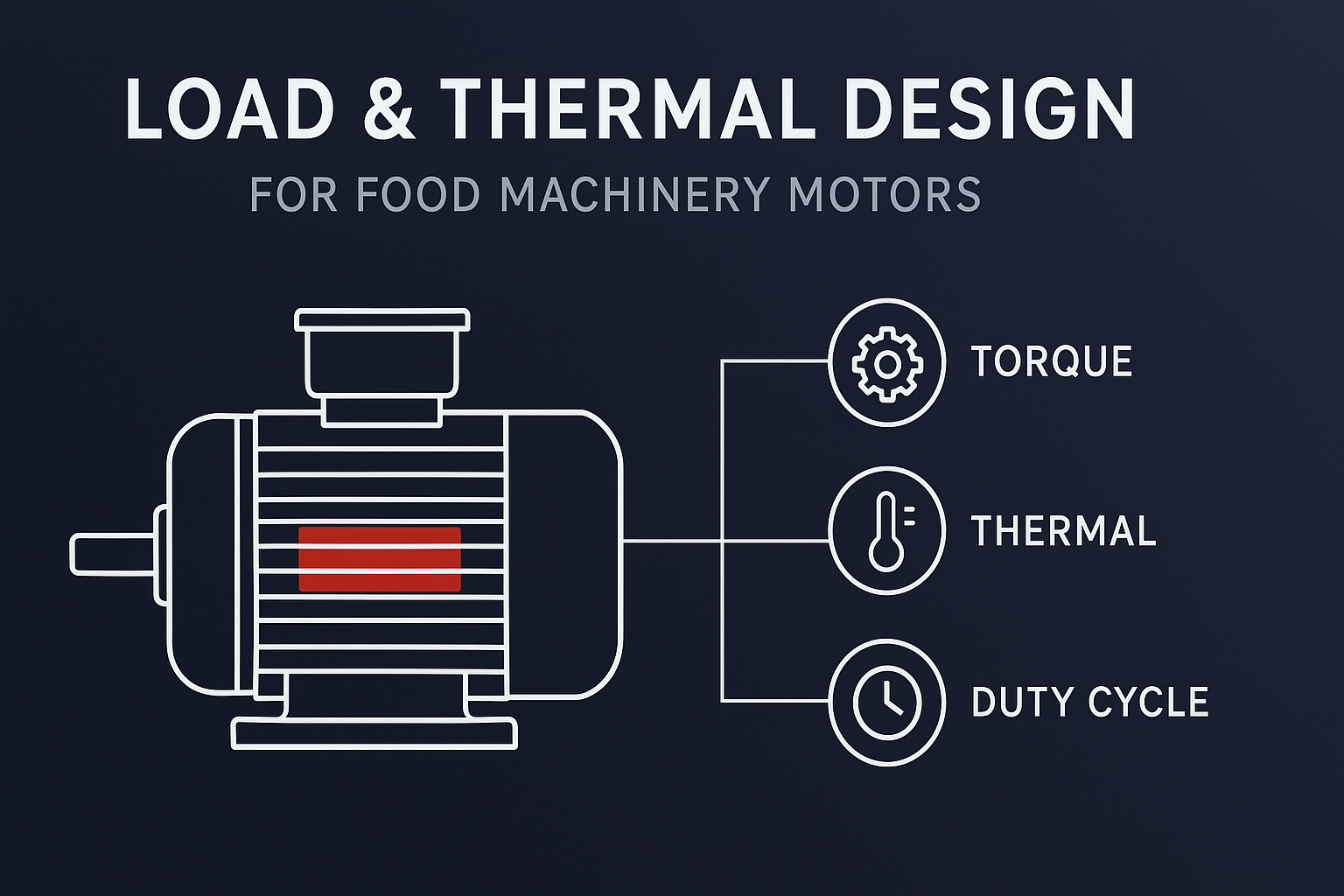
The Nominal Power Trap
Most sizing mistakes start with a shortcut: treating nominal power as the selection answer. In practice, many SIs overweight nameplate watts and underweight the real peak-season killer—start-stop transients that drive thermal accumulation. When starts get dense, the controller has to deliver higher phase current, copper loss rises as I²R, and temperature doesn’t fully bleed off between events. The result is nuisance derating/trips that show up late in commissioning or after ramp-up—especially on non-standard lines where duty assumptions don’t match reality.
This guide is for logistics system integrators (SIs) and operations teams who want a practical way to select a 24VDC drum/roller motor—by linking motor parameters to two outcomes you’re measured on: Throughput and System Availability.
Common selection mistakes are predictable. Here are three to watch for (wrong move → impact → what to do instead):
- Sizing by nominal power alone → start-stop transients drive heat accumulation, then derating/trips show up during ramp-up → define starting torque + duty cycle and validate against your real burst pattern.
- Ignoring duty cycle and thermal headroom → winding temperature never “resets” between dense starts, accelerating insulation aging → size for S1-style thermal stability and confirm with on-site temperature measurement.
- Ignoring service/TCO mechanics → cabinet complexity and slow replacement scale with roller count, inflating commissioning labor and downtime minutes → quantify install and swap time, then choose architecture/interface to protect availability.
To keep the discussion concrete, I’ll reference one platform: the Intelligent 24VDC Drum Motor & Roller Motor based on an integrated-drive BLDC architecture (integrated speed controller, decentralized control). We start with your Duty Profile (load × cycle × environment) and then choose the motor architecture that holds up when the line is busiest.
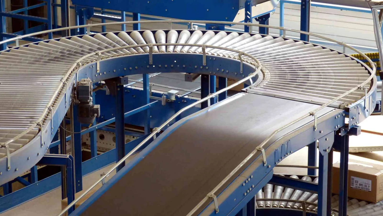
Why Traditional AC Struggles in Modern Sortation Lines
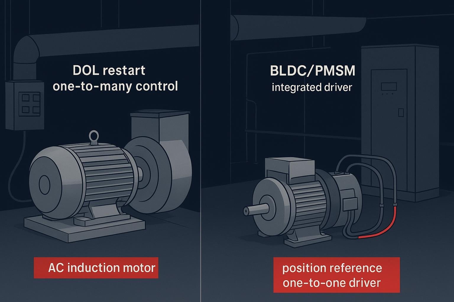
Traditional AC conveyor architectures push complexity upstream: cabinets, drives, and long cable runs become the “hidden project” inside your project. In high-density sorting lines, that centralized approach becomes a physical constraint—space, wiring, and troubleshooting time all scale with roller count.
A 24VDC integrated-drive BLDC architecture flips that constraint. By putting the speed controller at the roller (decentralized control), you reduce reliance on large external control cabinets and the bulk wiring that comes with them. For system integrators, this isn’t a styling choice—it reduces integration variables and installation touchpoints on complex, non-standard line builds:
- Less cabinet dependency reduces layout pressure in dense zones.
- Simplified wiring reduces the commissioning error surface area.
- Decentralized architecture aligns better with modular conveyor builds where zones are added, changed, or swapped during ramp-up.
On the safety side, 24VDC is touch-safe compared with higher-voltage conveyor lines that carry higher shock risk and often require more costly protective routing.
On the operating-cost side, the control logic matters as much as the motor. In North American automated warehousing, OEMs often prefer integrated conveyor motors that support ZPA (Zero Pressure Accumulation) logic: the roller only runs when a parcel arrives, and stays at zero energy consumption when idle. Versus traditional always-on AC approaches, this architecture is designed to deliver more than 50% energy savings in many zoned, high-idle scenarios through duty-cycle control—results depend on parcel arrival patterns, zone logic, and system tuning (and should be validated against your site’s actual duty cycle and measurement method).
If your line is zoned and idle time is non-trivial, ZPA is not a “nice to have.” It’s the main driver behind the energy model.
What to Specify: A 24VDC Selection Decision Matrix
Below is the specification table I expect an SI to fill before locking a drum/roller motor selection. Several values are application-defined; the purpose is to force clarity without inventing numbers.
| Parameter | What you must define | Why it matters (Throughput / Availability impact) |
|---|---|---|
| Power | Required mechanical output at the roller under worst-case load | Power is the budget, but it doesn’t predict startup success under high inertia. Treat it as a boundary, not a decision shortcut. |
| Starting torque | Peak torque required to break static friction and accelerate the parcel/roller zone | Directly governs whether zones start cleanly during peak, or stall/overheat into protective behavior that kills throughput. |
| Running torque | Torque required to maintain target speed under steady parcel flow | Determines speed stability under load; instability creates gap variation, affecting sorter timing and accumulation behavior. |
| Speed range | Target conveyor velocity range and control resolution | Speed range affects buffer timing and merge logic. Control resolution affects parcel spacing and mis-sort risk. |
| Duty cycle | Start/stop frequency and run/idle ratio (especially under ZPA) | Duty cycle drives thermal loading. Wrong assumptions here shorten seal life and trigger thermal protection events. |
| Ambient temperature | Worst-case ambient + enclosure effects (dust, washdown, restricted convection) | Ambient limits define thermal headroom. If you ignore them, you’re designing for the lab, not the peak-season floor. |
| Installation interface | Self-aligning spring-loaded shaft interface + replacement procedure | Replacement time determines how long a zone stays down. This is an availability input, not a mechanical detail. |
| Noise level | Required acoustic limit in personnel-dense stations | Noise influences operator acceptance and site compliance; also correlates with drivetrain quality under certain failure modes. |
| Non-standard validation | Which variables are outside the “catalog” envelope (roller length, shaft ends, duty peaks, contamination, airflow restrictions) and what evidence proves the match | Custom lines fail when assumptions go untested. Require a verification step (e.g., inertia matching + thermal margin check) before you lock the build. |
Two selection notes that should be explicit in every non-standard project:
- Power is the boundary. Starting torque is the soul. Nameplate watts tell you the steady-state budget, but they don’t guarantee a clean heavy-load start during peak accumulation.
- Validate inertia matching, not just torque. For non-standard conveyors, require an inertia estimate for the driven roller/parcel zone and check that your torque-to-inertia ratio supports the system’s response window. This is where a supplier’s FEA-backed magnetic-circuit design and verification workflow matters: you’re aligning motor dynamic response with the sorter’s control assumptions, not just hitting a catalog point.
If your conveyor sees long, repetitive operation with frequent starts under load, you’re effectively closer to continuous-duty (S1) thermal expectations than short-time duty (S2) assumptions. In practice, selecting around S1-style thermal stability helps keep winding temperature predictable; S2-style sizing can look fine on paper but run hotter when start events are dense and cooling time is limited. The key limitation is that S2 assumptions rely on defined run time and adequate rest, which start/stop logistics lines often don’t provide.
For peak-season tolerance, it’s often safer to choose a platform engineered with S1-style thermal headroom (continuous-duty redundancy) so frequent start/stop transients don’t consume your thermal margin as quickly.
This is an engineering interpretation based on duty definitions and the heat-balance behavior described below; confirm with on-site temperature measurements for your actual cycle profile.
In high-frequency start/stop lines, temperature doesn’t “reset” between events. What matters is the motor’s thermal time constant—how quickly winding heat builds and how slowly the assembly rejects it when a zone goes idle. In other words, temperature rise is a heat-balance problem (heat in vs. heat out over time): repeated accelerations can add losses faster than the motor can shed them.
As a practical check, treat cooldown as an explicit part of the duty cycle. In high-load, frequent-start scenarios, a 30–60 minute cooldown window is a conservative planning reference—not a guarantee. Actual cooldown time depends on load, ambient temperature, airflow, and how enclosed the roller/motor is, so validate it with on-site temperature measurements.
Turning parameters into outcomes: how specs map to system performance
A useful selection framework ties each input to a failure mode you can actually see on-site:
- Throughput collapses when start events become non-deterministic (stalling, late acceleration, inconsistent zone timing).
- Availability collapses when maintenance or replacement time scales with roller count, or when contamination forces unplanned shutdowns in clean logistics (food, pharmaceutical).
This is why the platform strategy matters. A drum motor built for logistics sorting is not just a motor with a speed rating; it is an engineered response to repeated transients.
Key Selection Judgments: Starting Torque vs Nominal Power in ZPA Lines
Inertia matching for a 200 ms response
In a modern sorter, a late zone response is not a minor deviation; it’s a spacing error that propagates downstream. When inertia matching is off, two things happen under high-frequency start/stop:
- The zone takes longer to accelerate than the control system assumes.
- The motor compensates with higher current and heat, pulling you toward thermal limits and nuisance stops.
Seen end-to-end, the failure chain is usually:
high load → frequent start/stop → heat accumulation → ΔT rise in the windings → insulation aging → protective derating/trips.
Here’s the missing link between frequent starts and heat accumulation. A start event typically demands higher torque than steady running (breaking static friction and accelerating inertia). To produce that torque, the controller drives higher phase current. As current rises, copper loss in the windings rises as I²R—so a relatively small current increase creates a disproportionate increase in heat.
If starts are dense (or the zone has limited idle time), that heat doesn’t fully leave the assembly before the next start. The result is cumulative winding temperature rise (heat in > heat out), which accelerates insulation aging and makes thermal limiting (derating or trips) more likely during peak periods.
For the Intelligent 24VDC Drum Motor & Roller Motor platform, the engineering intent is to maintain fast dynamic response under frequent start/stop operation. In practice, that means paying attention to the torque-to-inertia ratio—so the motor can break static friction immediately without the current spikes that often trigger thermal protection events.
We support this by using magnetic-circuit simulation (FEA) as part of the design approach to maintain predictable dynamic behavior.
This matters commercially because it affects whether you can commission to the sorter’s timing model without endless parameter chasing.
Starting torque vs nominal power
Selection mistakes often come from overweighting “nominal power” while underweighting the real event that kills conveyors in peak season: heavy-load start.
For a roller zone, the decision priority should be:
- Can the zone start reliably under worst-case accumulation and friction?
- Can it repeat that start profile across the duty cycle without thermal runaway?
An integrated speed controller is not only about simplifying wiring. It’s also where you manage startup behavior and current delivery in a way that supports reliable repeated starts.
When your line is start/stop dominated, document the starting torque requirement as a first-class input. If you can’t define it, you’re not ready to select a motor.
How to Quantify ROI: Installation and Maintenance TCO
Selection mistakes aren’t only technical—they become financial once you scale roller count. The fastest way to translate engineering choices into ROI is to express them as commissioning minutes, replacement minutes, and downtime risk.
Common selection pitfalls that create downtime and hidden cost
1. Ignoring duty cycle and seal longevity under frequent start/stop
A common field story looks like this: the line runs for months, then rollers start showing oil marks near the edges. Noise rises over time, and eventually a motor seizes during a peak window.
The engineering chain behind that story is consistent—especially when the line is non-standard and runs closer to its thermal limits:
- Frequent start/stop drives thermal cycling at end-caps and sealing interfaces.
- Thermal cycling + load shocks increase material fatigue (compression set / loss of elasticity).
- Reduced sealing margin raises the probability of leakage and contamination, which is unacceptable in food and pharmaceutical logistics.
One practical mechanism can be summarized as a simple chain you can validate on-site:
- Thermal cycle → repeated temperature swings at end-caps and sealing interfaces
- Material fatigue → loss of elasticity / compression set over time
- Pressure loss → reduced contact pressure and sealing margin
- Contamination ingress → higher leakage risk and cleanliness non-compliance
The exact rate depends on shaft speed, lubricant compatibility, and the site’s washdown/dust conditions.
The mitigation is architectural.If you model thermal behavior in contaminated or low-ventilation environments (oil mist, dust buildup, restricted airflow), it’s reasonable to run a sensitivity case such as “assume a 15–20% increase in effective thermal resistance” to see how much margin you lose. This is an engineering assumption for simulation, not a universal measured value—validate against on-site temperature measurements whenever possible.
An oil-free direct-drive approach reduces contamination vectors at the source (no chain/belt dust or oil carryover) and can be a better fit when your duty profile is heavy, start-stop dominated, and cleanliness-constrained. In addition, sealed, maintenance-free designs with a design life over 30,000 hours (manufacturer design target—dependent on load profile, environment, and temperature) are aligned to 24/7 logistics duty expectations.
2. Treating high-voltage cabinets as “someone else’s problem”
If you put a heavy AC motor into a light parcel line because the unit price looks good, you often pay for it later in cabinet space, VFD commissioning, and wiring labor.
This is where quantified project economics matter. With a traditional external motor installation and commissioning flow, you may spend 15 minutes per unit. With a spring-loaded shaft interface designed for rapid replacement, the installation time can drop to 0.5 minutes per unit, and the mechanical service model shifts.
At scale, the labor math is not subtle. Using the same illustrative assumptions above (15 minutes vs. 0.5 minutes per unit), a 2,000-roller project comes out to roughly 480 labor-hours saved—about $24,000 at $50/hour.
This $24,000 saving is a baseline—contact a qualified conveyor engineering team for a custom TCO calculator based on your local labor rates and roller count.
This is a worked example, not a guarantee—replace the assumptions with your site’s verified installation time, labor rate, and replacement workflow. The core point is how technical choices (wiring topology, replacement interface, contamination risk) roll directly into TCO through commissioning hours, downtime minutes, and maintenance touches—not just motor purchase price.
Example summary (replace with your data):
| Item | Value | Notes |
|---|---|---|
| Install time per unit (traditional) | 15 min | Worked example assumption |
| Install time per unit (spring-loaded) | 0.5 min | Worked example assumption |
| Roller count | 2,000 | Example project scale |
| Labor-hours saved | ~480 hours | From time delta × units |
| Labor rate | $50/hour | Example rate |
| Labor cost impact | ~$24,000 | 480 × 50 |
If a supplier’s MTBF numbers are not backed by auditable validation, a peak-season cluster failure can cost more in one hour than the entire delta between architectures.
When to Choose Standard vs Custom 24VDC Platforms
Use this section as an explicit boundary-setting tool for SIs. You’re deciding whether a catalog platform is “enough,” or whether your duty profile and mechanics require verification-driven customization.
If the environment is moderate and takt time is stable
Choose a standard integrated platform when:
- Duty is predictable (no dense start-stop peaks) and load doesn’t frequently exceed nominal assumptions.
- Ambient/airflow is normal and contamination risk is low.
- Interfaces are standard (roller length, shaft ends, mounting envelope).
If you need fast response, overload tolerance, or non-standard mechanics
Treat it as a custom/ODM problem when one or more are true:
- You need a <200 ms response window with dense start-stop transients.
- The line frequently sees heavy accumulation (high friction, repeated overload starts).
- You have non-standard mechanics (special shaft ends, non-standard roller length, tight space envelopes).
- You’re operating in harsh conditions (high contamination or restricted convection) where thermal margin shrinks.
In those cases, require a verification workflow (inertia matching + thermal margin check). This is also where FEA-based magnetic-circuit simulation helps de-risk the build by ensuring the motor’s dynamic response and the control algorithm assumptions stay aligned.
Prototyping lead time: keep commissioning schedules intact
Logistics conveyor builds don’t fail because engineers can’t design. They fail because lead times and rework push commissioning into a corner.
For customization work (non-standard length, special shaft ends, protection-level adjustments), clarify expected sample lead time early. For example, if you’re evaluating Honest, request the current sampling lead-time estimate (often quoted around ~4–6 weeks as a general OEM/ODM reference, scope- and material-dependent) and confirm it against your project timeline.
For risk control, ask what validation evidence supports the platform you’re selecting. For example, some suppliers cite validation programs that include millions of frequent start-stop cycles; if this matters for your application, request the applicable test conditions, acceptance criteria, and any available documentation.
Selection notes to validate with your supplier
- Start-stop cycle testing evidence (e.g., reported 3,000,000+ cycles; confirm conditions)
- Design life targets (e.g., 30,000 hours; duty/environment dependent)
- Replacement workflow assumptions (e.g., ~0.5 minute per unit in a worked example; site-dependent)
Quick decision matrix for SIs: match the architecture to the job
Use this as a fast “scene match” before you dive back into specs:
- If your line is high-frequency start/stop and you have cleanliness constraints (food / pharma), prioritize integrated-drive BLDC with an oil-free direct-drive architecture to reduce contamination vectors.
- If you’re constrained by commissioning time or maintenance labor, prioritize a self-aligning spring-loaded shaft interface to shorten install and swap time at scale.
- If you run continuous load in high ambient temperature zones, prioritize S1-style thermal headroom and FEA-informed matching so transient starts don’t push you into nuisance thermal protection.
ROI drivers for sortation conveyors
A 24VDC integrated-drive drum motor is a future-proofing move when it is selected for the right reasons:
- Energy model: ZPA logic can drive >50% energy savings in zoned systems with meaningful idle time (site-dependent; validate against your parcel arrival patterns, zone logic, and measurement method).
- Uptime model: sealed, maintenance-free design with >30,000 hours design life (design target; duty/environment dependent; confirm the test conditions/derating guidance in the datasheet) supports 24/7 operations.
- Service model: spring-loaded shaft enables rapid replacement that protects availability.
- Contamination model: oil-free direct drive reduces contamination risk for clean logistics requirements.
- Thermal model: the architecture supports intelligent thermal management—helping the system maintain throughput by optimizing output during thermal transients rather than hard-stopping (implementation and limits are configuration-specific).
Ready to optimize your sorting line? Before you contact us, prepare this engineering requirements checklist so we can size the 24VDC drum/roller motor to your real duty profile (not a nameplate shortcut):
- Parcel profile: typical and max parcel weight, coefficient of friction assumptions, worst-case accumulation condition
- Duty cycle: starts per hour, run/idle split under ZPA logic, peak-season burst pattern
- Space envelope: roller length, mounting/interface constraints, any special shaft-end requirements
- Environment: ambient temperature, airflow/restricted convection, dust/washdown/cleanliness constraints
We’ll return:
- An inertia-matching summary for the 200 ms response target
- A TCO comparison that separates energy (ZPA duty), commissioning labor, and service/replacement time so you can compare architectures on the same basis
If you need the broader system context, start from the Honest Motor Conveyor & Sorting System motor solutions page.