Why do motor prototypes pass initial tests but fail during system validation?For a food machinery OEM, the answer is rarely “engineering effort.” It’s iteration driven by a mismatch between the motor’s assumed operating point and the machine’s real load profile.
A motor prototype can look fine on nameplate parameters (rated torque, rated power), then fail once you validate the full duty cycle: repeated start events, impact torque spikes, and thermal boundary conditions that don’t exist on a bench test.
The schedule risk isn’t delivery speed. It’s building the first prototype before the motor is matched to the load profile, duty classification, and thermal boundary. When those inputs are wrong or incomplete, the first “working” motor often becomes a late-stage redesign—exactly when certification testing and NPI gates are closest.
Boundary note on lead time: The cycle times described below assume an existing electromagnetic platform library (including mature 110/120/145 frame families).
If your project requires new mechanical tooling, lead time should be evaluated separately based on tooling complexity.
Why Motor Prototypes Delay NPI
In commercial food machinery, the most expensive schedule slip often starts as a “small” motor selection shortcut: procurement locks on static specs (rated torque, rated power, a generic duty note), then the first prototype is validated only after integration.
The failure mode shows up late—and it is rarely subtle.
- Certification and validation surprises: temperature-rise and abnormal-operation issues are often discovered late in system-level testing or certification workflows such as UL 763. (For context on scope, see UL’s description of UL 763 for motor-operated commercial food preparing machines.)
- Re-selection cost: pursuing a low-cost standard motor can trigger a full re-selection loop when the electromagnetic solution does not match the actual load profile.
Iteration occurs when motor selection is based on static ratings. In reality, the application is governed by dynamic load variation and thermal accumulation.
In summary, iteration is not driven by motor quality. It results from a mismatch between selection assumptions and real operating conditions.For an R&D director or program manager, the root concern isn’t theoretical. It’s concrete:
- “Will the motor still have thermal margin after an hour of real operation?”
- “Are we accidentally running an S2 15 min duty assumption as near-S1 continuous operation?”
- “Does the design account for the duty’s peak impact events—or only the rated point?”
When those questions are answered only after the prototype is built, iteration becomes the schedule.
Why Static Motor Selection Fails
Iteration is a symptom. The upstream cause is a mismatch between what the motor was selected for (static nameplate points) and what the machine actually does (dynamic load + real thermal boundary).
NPI Phase Quick Troubleshooting Guide
If a motor prototype “passed” in a component test but fails during system validation, use the table below to narrow the cause quickly before you start a full re-selection loop.
| Step | Check item | What you’ll see in validation | Likely cause | What to do next |
|---|---|---|---|---|
| 1 | Boundary conditions match the test plan | Failure only appears in hot ambient or restricted airflow | Thermal boundary mismatch (ambient, airflow, fouling) | Re-run at the defined ambient (often ~45°C for food machinery) with representative airflow and enclosure assumptions |
| 2 | Duty type and run profile are correct | Temperature rise looks acceptable early, then drifts upward over time | Duty-cycle misclassification (S2 assumed, near-S1 in use) | Reclassify duty per IEC 60034 terms and validate thermal margin at the true cycle |
| 3 | Start and transient torque margin | Stall, nuisance trip, or overcurrent during loaded start or impact events | Start torque sized to rated point; impact torque not captured (T_{max}) | Instrument start events, extract peak torque, then re-match starting margin to worst-case transient |
| 4 | Peak impact events are represented | Failures correlate with hard inclusions or product jams | Missing impact-load cases in the validation script | Add an “impact load” segment to the validation sequence and correlate electrical/thermal response |
| 5 | Mechanical interfaces and alignment | Noise, rub, or intermittent stalls after integration | Mounting/alignment changes or tolerance stack-up at system level | Verify mounting, shaft alignment, and interface tolerances under real assembly conditions |
| 6 | Thermal measurement visibility | You only see pass/fail or trip, not the temperature trajectory | No winding temperature observation; dominant limit is hidden | Use an instrumented prototype (e.g., embedded thermistors) to observe winding temperature in real time |
A more reliable approach shifts the engineering starting point earlier in the process. Instead of starting from a catalog specification and hoping the prototype survives, the process begins with dynamic load profiling. This is translated into electromagnetic and thermal boundaries that are reviewed as a short, auditable input set before the first build.
To eliminate redundant iteration, Honest Motor has codified this shift from static sourcing to dynamic load profiling into a standardized front-end engineering workflow. This ensures that the dynamic load is the primary driver of the OEM engineering process from day one.
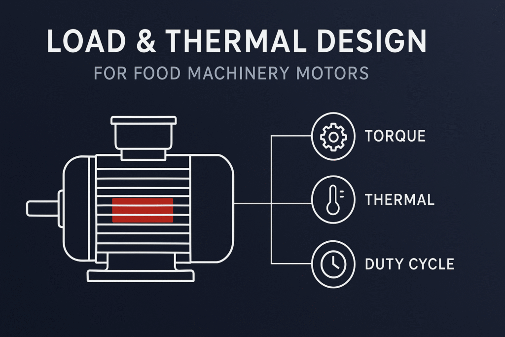
1.Start Torque Is a Critical Risk
Food machinery loads are not smooth. A meat grinder that encounters hard inclusions produces a peak impact torque ((T_{max})) event. If the design was matched to rated torque only, that impact becomes a stall/overcurrent/thermal event.
Load profiling should prioritize peak impact torque extraction, and starting requirements should be defined against the maximum expected transient load (T_{max}), with sufficient margin to avoid stall under worst-case conditions. In practice, this is treated as a key design target when tuning winding and rotor parameters on an existing platform.
Depending on the application, starting capability is often sized at ~2.0–2.5× the torque required at the critical start condition (described as typical practice, not a guarantee).
2.Thermal Boundary Must Match Real Conditions
A motor that passes a controlled lab run can fail in a kitchen environment for one simple reason: the thermal boundary is different.
In high-ambient food machinery applications, validation is often anchored at ~45°C ambient, and thermal validation is treated as a boundary-condition problem—explicitly defining ambient temperature, airflow condition, and surface fouling assumptions.
That boundary is then adjusted for heat-transfer degradation caused by low convection and grease/dirt accumulation that reduce the effective convective coefficient (h).
In practice, this moves thermal risk from “field surprise” to an engineering check you can review before committing to a build.
For temperature-rise limits and measurement methods, many engineering teams also cross-check against widely cited guidance from standards bodies such as NEMA; see NEMA’s Alternating Current Motors in Detail (temperature effects and temperature-rise discussion).
3.Wrong Duty Cycle Assumptions Cause Failures
Common Pitfalls That Create Late-Stage Iteration
Most prototype failures in system validation aren’t “mysteries.” They come from a small set of repeatable shortcuts:
- Selecting by nameplate only: rated torque/power looks adequate, but the real cycle includes starts, impacts, and thermal accumulation.
- Treating duty as a procurement note: the application behaves like near-S1, but the motor was assumed as S2 (or similar short-time duty).
- Validating in a friendly thermal boundary: lab airflow and clean surfaces hide the heat-transfer penalties of grease/dirt accumulation and low convection.
- Ignoring peak impact torque: impact events (T_{max}) are not represented, so the first time the system sees a jam the motor becomes the fuse.
A common prototype trap is duty-cycle misclassification: an application is specified as S2 15 min, but the end use behaves like near-S1 continuous operation. Duty classification should follow IEC 60034 definitions (e.g., S1 continuous duty vs. S2 short-time duty), rather than procurement assumptions. (See the IEC 60034-1:2022 sample preview for duty-type terminology.)
In OEM engineering workflows, this assumption is explicitly audited because duty drift is a fast path from “prototype seems fine” to a late-stage temperature-rise failure.
Turn Load Data Into Early Estimates
Early in the program, based on the load description you provide (e.g., mixing resistance, start frequency), a team can generate a preliminary electromagnetic + thermal balance estimate. The purpose isn’t to guarantee final certification performance—it’s to identify mismatch risks before a prototype is built, when changes are still inexpensive.
This is commonly implemented as a short pre-design review before the first build.
Avoid Re-Tooling with Platform Design
In programs with compressed lead times, the key engineering question becomes: which part of the design loop is actually consuming time?
Standard Catalog Motor vs. Tuned Platform
A useful way to reduce iteration is to be explicit about what you’re buying:
| Selection approach | What it optimizes for | Typical failure mode in food machinery validation | When it makes sense |
|---|---|---|---|
| Standard catalog motor | Lowest unit cost and fastest initial sourcing | Late surprises: start events, impact torque, and thermal boundary don’t match the “rated point” assumptions | Truly steady loads, generous thermal boundary, and low consequence of rework |
| Tuned platform on a mature frame family | Predictable validation path and reduced rework | Requires upfront load profiling and boundary definition | Compressed NPI schedules, high risk of certification surprises, or when mechanical interfaces must stay fixed |
Decision boundary: if the mechanical interface is fixed (mounting envelope can’t change) and your validation plan includes hot-ambient operation plus transient load events, a tuned platform approach usually reduces total iteration time—even if the unit price is not the minimum.
In non-standard motor projects, the longest delays usually come from mechanical rework: housing changes, end-bell changes, or lamination tooling changes.
A common approach is platform-based micro-customization on mature electromagnetic platforms, enabling adjustments to electromagnetic behavior without reopening mechanical interfaces or tooling.
To achieve this without reopening tooling, mature 110/120/145 electromagnetic platform architectures are typically used.
At Honest Motor, this is implemented through an internal platform library to support controlled micro-customization of electromagnetic performance.
Keep Prototype Cycles Predictable
For an instrumented prototype stage, teams typically build on mature platforms and perform controlled electromagnetic tuning:
- adjust the winding design (e.g., wire gauge)
- adjust slot fill / flux density targets
- within the existing frame envelope, rematch performance by tuning wire gauge and stack length
This approach reduces variability in prototype cycles by avoiding mechanical rework. This is often achieved by keeping changes inside an existing frame (e.g., 110/120/145) rather than reopening lamination tooling.
This is the specific value translation for food machinery OEMs:
- By adjusting wire gauge and slot fill to provide sufficient starting margin relative to peak load conditions (typically in the range of 2.0–2.5× depending on application), the motor can handle cold-start and loaded start conditions (e.g., frozen meat start in a grinder).
- Because the work is contained inside the existing platform envelope, the mechanical mounting dimensions can remain unchanged—avoiding a mechanical rework loop that typically adds weeks to the program.
Reduce Lab-to-Field Failure Risk
When a prototype arrives as a black box, validation often becomes a prolonged loop: install → test → fail → iterate.
The program may not fail because the motor is fundamentally wrong, but because the prototype provides no visibility into the dominant failure driver early.
One widely used approach is an instrumented prototype, designed to make validation auditable.
Use Instrumented Prototypes
In the instrumented prototype stage, a platform-based prototype can include embedded temperature sensors—specifically thermistors—so your system test can read winding temperature in real time.
This matters because temperature-rise and trip behavior are rarely binary. With embedded temperature observation:
- you can correlate load events (including impact load) to thermal response
- you can identify whether the limiting factor is electromagnetic margin or thermal boundary
- you can close the loop in a single validation sequence instead of stretching a “test–fail–modify–retest” cycle across months
Validate Under Real Conditions (45°C + Load)
After prototype delivery, field-simulated validation can be run against the defined boundary conditions. In many OEM engineering workflows, this is packaged as a documented validation sequence:
- 45°C ambient boundary
- impact load condition
- a repeated-cycle endurance loop
- outputs a complete test package
The intent is straightforward: reduce the lab-to-field mismatch by validating in a boundary closer to real back-of-house conditions, then provide an auditable package you can use for internal reviews and compliance preparation.
Move Validation Earlier to Avoid Redesign
When the process is load-driven and validation is instrumented, iteration becomes the exception.
The objective is for the A-sample to be close to mass-production readiness, which can significantly reduce the likelihood of late-stage redesign and certification surprises—not by claiming the lab result in advance, but by removing the most common blind spots (impact torque, duty-cycle drift, and thermal boundary mismatch) before the build.
How to Use Load Profiling for Motor Selection
If current motor RFQ processes are still anchored on static specifications, one practical improvement is to convert “load assumptions” into a shared engineering artifact early in the NPI cycle.
A structured load profiling checklist can be used as an internal NPI gate input to reduce iteration risk across electrical and thermal validation stages.
To support implementation, a standardized Load Profiling Checklist is commonly used as an NPI input structure in OEM workflows, and a preliminary 48-hour thermal estimate can be provided based on submitted dynamic load parameters.
The checklist typically includes:
- peak impact torque definition (Tₘₐₓ)
- starting condition definition and required starting-torque margin
- duty-cycle classification audit (S2 vs. near-S1 continuous behavior)
- thermal boundary definition (ambient temperature, airflow condition, and fouling assumptions)
By structuring load assumptions as a formal NPI input, motor selection becomes a predictable engineering process rather than a trial-and-error iteration cycle.