When someone says they “need better torque control,” they usually aren’t asking for a prettier speed loop. They’re asking for one thing: force that stays predictable when load, friction, and the operating point drift during real operation.
That’s why torque control shows up in web handling, force testing, precision pressing, and any process where “close enough” speed still makes bad parts.
In this guide, we’ll keep it practical. You’ll learn what torque control actually regulates, how it differs from speed and position modes, where it breaks down when the load changes, and what to check when you’re choosing a motor + drive stack.
Here’s a quick analogy: when you tighten a screw by hand, you don’t really care about RPM or turns. You care whether the clamp force feels right. Torque control works the same way—regulate force, and let speed and position be the outcome.
Torque control in plain terms: regulate force, not motion
Torque control is a control mode where the drive’s main job is to regulate motor torque output—which usually means regulating mechanical force through your mechanism—rather than holding a target speed or position.
In other words, torque is often the most practical proxy for force—but the torque-to-force relationship depends on your mechanics (radius, efficiency, friction, compliance). If you need true force accuracy, you typically close the loop with a load cell or force sensor.
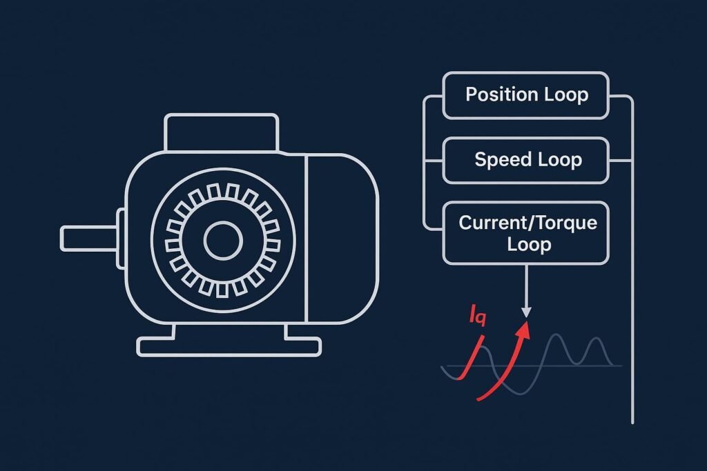
In most industrial drives, torque control is implemented by regulating current in the innermost loop. In a cascaded servo architecture, the current loop sits inside the velocity loop, which sits inside the position loop. Motion Control Tips outlines this nested structure (and the usual bandwidth rule: current faster than velocity, velocity faster than position) in its FAQ on current, velocity, and position loops.
As a rough benchmark, many industrial FOC/servo systems target a current-loop (torque-loop) bandwidth on the order of ~1–3 kHz, with the velocity-loop bandwidth roughly an order of magnitude lower (often ~100–600 Hz, depending on mechanics and stability margins). Microchip’s FOC tuning notes summarize this current-loop range as typical for industrial drives, and Motion Control Tips discusses the nested-loop bandwidth separation used in servo architectures.
Torque accuracy begins with the current loop
At the physics level, electromagnetic torque is tied to current. In field-oriented control (FOC), the torque-producing component is the quadrature-axis current (often described as Iq), while the direct-axis component (Id) is managed to control flux depending on the motor type and operating region.
Yokogawa’s application note on measurements for field-oriented control explains the d/q-axis framing and why aligning current appropriately is fundamental to maximizing usable torque.
What this means in practice:
- If the current loop is slow (or poorly measured), torque commands become “soft” and delayed.
- If current measurement is noisy or biased, you don’t just get current error — you get torque ripple and force variation.
If you care about force repeatability, your “torque mode” is only as good as your current loop bandwidth and your current sensing fidelity.
Where torque control makes or breaks production
Torque control isn’t a “nicer way to drive a motor.” It’s a way to make a process variable stable when speed control can’t.
Maintain web tension without chasing speed
If you’re controlling tension in unwind/rewind, coating, printing, or slitting lines, the variable you’re trying to hold constant is web force, not roller speed.
Hold constant force in pressing and sealing processes
Not every force-critical process looks like “tension control.” In laminating, heat sealing, crimping, or controlled pressing, what you actually care about is repeatable normal force at the tool—so parts bond, seal, or fit the same way every cycle.
Torque mode helps because it gives you a direct handle on the actuator effort. Through a ballscrew or press mechanism, motor torque is converted into linear thrust. If friction, temperature, or material thickness changes, a well-designed torque loop can keep the applied force more consistent than a pure speed loop (which tends to “push through” disturbances until something slips or deforms).
A practical takeaway: in force-critical presses, torque mode often works best when it’s paired with clear speed limits and (when required) a force sensor or load cell for higher accuracy than torque estimation alone.
Torque control becomes non-negotiable as roll diameter changes, because the torque-to-tension relationship changes with it. Mitsubishi Electric notes that keeping tension constant requires braking torque to vary with reel diameter—see the Mitsubishi tension control guide (PDF).
With closed-loop tension control, you go a step further: measure tension (load cell or dancer) and regulate the actuator (drive or brake) so commanded torque continuously cancels disturbances. Dover Flexo Electronics’ Tension Control 101 is a clear walkthrough of that feedback logic.
Common pitfalls in real tension systems:
- Treating tension like a “speed trim” problem, then wondering why it hunts when friction changes
- Underestimating how much torque ripple turns into tension variation at low line speeds
- Building the loop without a plan for saturation, diameter estimation, and transients
Keep force-controlled testing honest
In pull tests, compression tests, and press-fit characterization, small torque disturbances can show up as force noise at the fixture—and force noise becomes bad data.
Torque control tends to help when:
- stiffness changes across the stroke (fixtures, grips, overall compliance)
- friction isn’t stable (seals, guides, lubrication state)
- you hit stick-slip zones where speed control can amplify force oscillation
The goal usually isn’t “zero ripple.” It’s repeatable force within the bandwidth that matters for your measurement.
Torque mode vs speed mode vs position mode: pick what you’re trying to hold constant
All three modes can use the same hardware — the difference is which variable is treated as the “truth” and which loops are closed.
A simple decision logic: what’s your controlled variable?
In cascaded servo control, the loops are commonly structured as current (torque) inside velocity inside position. Motion Control Tips summarizes the loop structure and gives a useful bandwidth rule-of-thumb in its FAQ on current, velocity, and position loops.
Use this mental model:
- Torque mode: “Hold commanded torque.” Speed becomes whatever physics dictates unless you add limits. For example, if a press or web path suddenly sees higher resistance (thicker material, more friction, a tighter nip), the drive can maintain torque while the speed naturally drops—this is expected behavior, not a tuning failure.
- Speed mode: “Hold commanded speed.” Torque becomes whatever is required (up to limits).
- Position mode: “Hold commanded position.” Speed and torque are used as the means.
Practical implications engineers care about:
- Torque mode gives you direct control of force — but you own safety constraints.
- Speed/position modes give you motion predictability — but force may drift with friction, compliance, or load disturbances.
Torque control failure modes under load transients
Torque control behaves beautifully in steady state — and gets dangerous when assumptions break.
The classic risk: load disappears, torque doesn’t
If you command torque and the load suddenly drops (web breaks, a coupling slips, material releases), the motor can accelerate fast.
That’s just dynamics: torque creates angular acceleration. If the effective inertia seen by the motor suddenly collapses, the same torque command produces much higher acceleration.
In torque mode, “stable torque” can turn into “unstable speed” in a fraction of a second when the load path changes.
Treat it like a safety function: limits, detection, and torque removal
A robust torque-mode design usually includes at least two layers:
- Speed limiting / overspeed detection in the control logic (so torque mode can’t drive speed beyond an engineered ceiling)
- A safety-rated method to remove torque when conditions are unsafe
Practical commissioning checks to make this real (not just a concept):
- Verify the speed ceiling: confirm the drive/controller enforces a hard max speed (and what happens on fault).
- Define loss-of-load triggers: web break, coupling slip, or sudden torque drop should trip a reaction (limit, ramp down, or torque removal) appropriate to the risk.
- Validate STO behavior: confirm STO wiring, response behavior, and restart conditions match your safety design and risk assessment (don’t treat STO like a normal stop).
A common safety function in motion systems is Safe Torque Off (STO), which removes the drive’s ability to produce torque. Control.com provides a practical explainer of Safe Torque Off for motion systems.
For additional high-level overspeed considerations (especially relevant when mechanical integrity and safe speed are critical), see the NIH technical bulletin on overspeed motors (2020).
Motor + drive selection: judge torque mode by behavior, not specs
You can’t judge torque-control performance from nameplate power and rated speed alone.
What actually determines torque controllability?
In real commissioning, these are the items that usually decide whether torque mode feels crisp—or mushy:
- Current loop bandwidth and latency (sets the ceiling for torque response)
- Current measurement architecture and error sensitivity (offset, gain mismatch, sampling timing)
- Torque ripple at the operating region you care about (especially low speed)
- Torque linearity across your working range (how proportional output torque is to command current/torque, especially at low torque)
- Feedback resolution and quality (encoder/resolver, observer design)
- Disturbance rejection under real friction and compliance
Analog Devices goes deep on why nonidealities show up as ripple: inverter dead time and current-sense offset/gain/timing errors can inject harmonics that become torque ripple; see A system approach to the impact of nonideal effects in a motor drive current loop.
To avoid mixing up concepts, it also helps to separate cogging torque (open-circuit, position-dependent) from energized torque ripple. Motion Control Tips clarifies that distinction in cogging torque vs torque ripple.
Match the stack to the operating condition
Torque control quality is a system property. When requirements get specific — e.g., ultra-low-speed smoothness, high-frequency force modulation, tight EMI constraints, or rapid on/off cycling — you often need to match:
- motor electromagnetic design (ripple sources, cogging behavior)
- drive switching strategy and sampling synchronization
- sensing (current, position, and sometimes torque/force sensors)
- mechanical design (compliance, backlash, diameter variation)
If your design includes gearing, selection becomes even more sensitive because the gearbox changes reflected inertia, friction, and the torque ripple seen at the load.
Torque control is the foundation of force-critical motion
If your process cares about force repeatability — tension stability, test validity, or controlled pressing — torque control is often the right foundation.
But torque mode isn’t “set torque and forget it.” One deeper takeaway is that all motion control ultimately cashes out as torque: position error is corrected by commanding acceleration (torque), and speed disturbances are rejected by adding or subtracting torque. That’s why the current loop and torque-producing current matter even when you run in speed or position mode.
Here’s the practical checklist to take with you:
- Make the current loop fast and measurable.
- Track down torque ripple sources instead of hand-waving them away.
- Be explicit about where torque mode ends and speed/position limits begin.
- Add safety layers so a load transient can’t turn torque stability into an overspeed event.
If you need a sanity-check on your torque-control architecture, the Honest engineering team can review your operating envelope (speed range, inertia, compliance, sensing, safety constraints) and help you define an approach that’s stable in the lab and reliable on the factory floor.