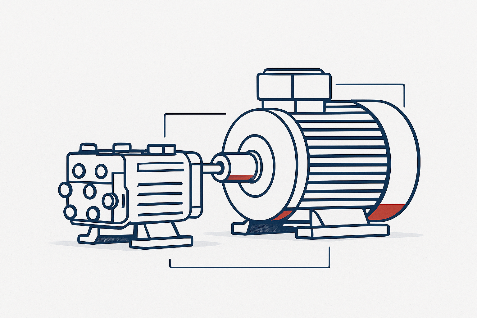
Industrial HVAC specifiers face a familiar choice: stick with proven AC induction motors or invest in BLDC/PMSM solutions for finer speed and torque control. This guide focuses on 0.75–2.2 kW, 4‑pole fans and pumps at 1500–1800 rpm under S1 continuous duty at 40°C ambient.
We examine drive schemes, restart behavior, control topology at scale, system BOM and wiring complexity, and how duty cycle impacts payback.
For fixed-speed systems, AC induction usually offers simplicity and predictable TCO. BLDC/PMSM can provide efficiency gains in continuously modulating systems, but for short-time S2 duty, the advantage often does not justify the added complexity.
Why AC induction remains a deterministic baseline for industrial HVAC and commercial equipment
AC induction motors are favored in HVAC because their restart behavior under real power events and their commissioning profile are predictable. A line-operated or VFD-fed induction motor can tolerate straightforward direct-on-line starting (where allowed) or conventional VFD ramp profiles. After a brief supply interruption, the machine does not require any explicit rotor position reacquisition to produce torque again; the electromagnetic system simply re-establishes a rotating field and the rotor re-couples through slip.
For procurement and service teams, that physical behavior usually shows up as fewer restart edge cases to qualify, fewer software states to validate, and a simpler troubleshooting tree when power quality is imperfect.
At the rated operating point for a 4-pole 0.75–2.2 kW machine under S1 continuous duty at 40°C ambient, modern IE3/IE4-class induction designs are typically already in the “good enough” regime for many fixed-speed fans and pumps. If the equipment lives near nominal speed and only trims occasionally, a few points of motor-only efficiency advantage from a PM machine can be diluted (or fully offset) once you account for the required per-motor power electronics, wiring, and commissioning burden.
The drivers of change: when BLDC justifies its system premium
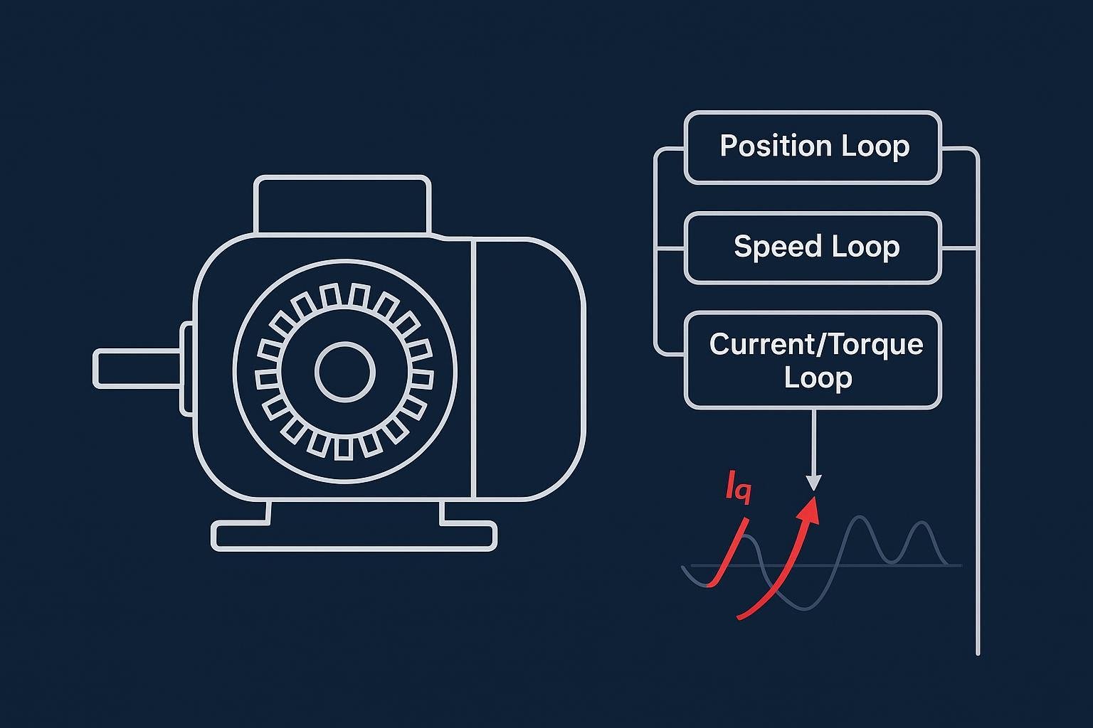
BLDC/PMSM becomes technically justified when you need fine, frequent speed regulation and strong part-load efficiency. With field-oriented control, torque quality remains stable and losses can be better managed across a wide operating band (often most relevant in the 30–80% speed region for variable-torque fan and pump loads).
Variable-torque loads such as fans and pumps follow affinity laws, where power scales approximately with the cube of speed. As a result, systems that spend significant time below nominal speed tend to amplify part-load efficiency differences between control strategies.
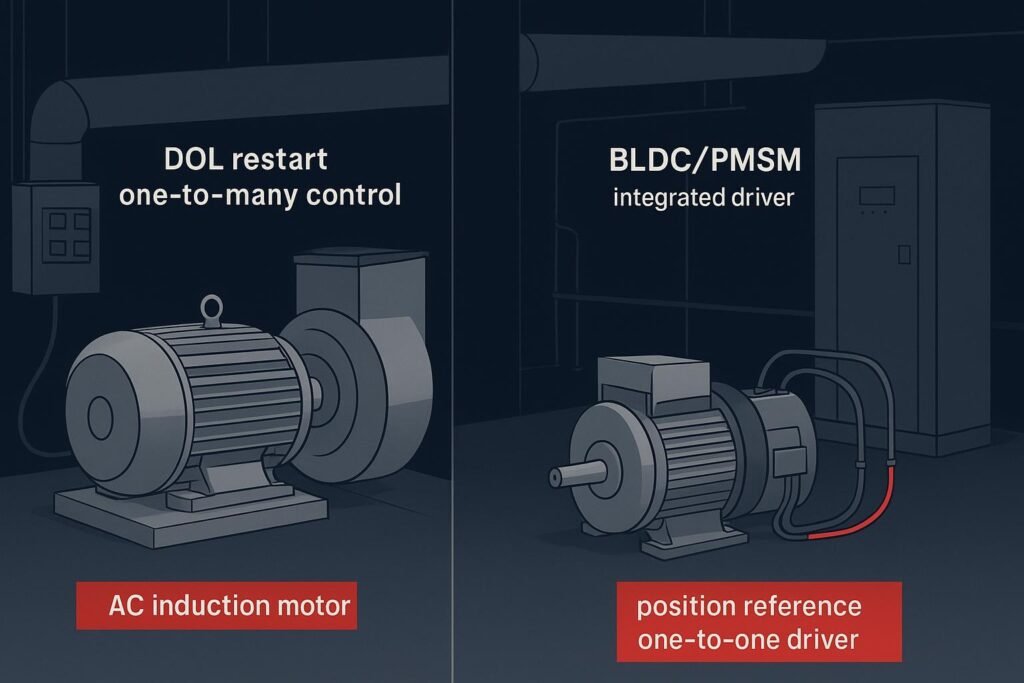
There is, however, a control barrier that engineering teams must plan for. After a power loss at (or near) zero speed, a BLDC/PMSM drive must establish rotor electrical angle before it can commutate correctly and build controlled torque. That is handled either by rotor-position sensors (Hall sensors or an encoder) or by sensorless startup routines such as alignment and initial position detection before transitioning to back-EMF or observer-based estimation. In practice, this means more commissioning variables, more edge cases around brownouts and coast-down restarts, and more value in treating “motor + driver + harness” as a single qualified system rather than mix-and-matching components.
The hidden cost of intelligence: analyzing the drive scheme barrier and control topology
Two architectural realities dominate HVAC deployments:
- Induction systems scale cleanly with one starter or one VFD per motor, coordinated by a shared control signal for group start/stop. Protection and maintenance are straightforward, and wiring remains minimal at the motor termination.
- PM/BLDC systems typically use one driver per motor in standard HVAC architectures. While multi-axis designs can share elements such as a DC bus in other industries, the common HVAC implementation still treats each motor as its own controlled and protected channel. For HVAC “motor clusters,” that usually means cabinet space, thermal design, and service procedures scale per motor rather than per group.
That’s not an abstract control choice—it’s a direct line item impact on cabinet layout, thermal management, EMC mitigation, spare parts strategy, and the number of things a technician must diagnose under time pressure.
Wiring reflects those choices. An AC induction motor typically needs three power conductors plus protective earth to the motor, while control I/O remains at the starter or VFD in the cabinet. A BLDC/PMSM system often adds a feedback harness (Hall or encoder) and additional driver I/O, increasing conductor count, connectorization, and panel landing points.
From a BOM perspective, the critical question is where the electronics live and whether they are optional. With AC induction at fixed speed, the electrical system can be as simple as a contactor plus overload protection. Add a VFD only if speed trimming or soft starting is required. With BLDC/PMSM, the power electronics are mandatory: rectification, an inverter stage, logic power, and protections are part of every motor channel.
Duty cycle as the ultimate decider for ROI
Duty type dictates whether premium electronics translate into savings. Under S1 continuous duty at 40°C ambient, systems that regularly modulate to optimize static pressure or flow can harvest part‑load efficiency benefits from BLDC/PMSM and its tuned control. In contrast, S2 short‑time duty (for example, 15–30 minutes per cycle with full cool‑down) seldom reaches thermal equilibrium; the short runtime blunts energy‑use differences while the driver still adds cost and potential failure points. IEC duty-type definitions (S1 vs. S2) provide the right lens for reading nameplates and writing specs: S1 is intended to reach thermal equilibrium; S2 is explicitly a short, defined run followed by a cool-down period.
Put simply: in S1 with frequent modulation, BLDC can pay back; in S1 fixed‑speed or S2 short‑time, AC induction is generally the more economical choice.
A cautionary S2 counterexample is commercial kitchen equipment such as mixers or slicers: the motor may run 15–30 minutes per prep cycle, then sit idle long enough to cool.
In that profile, the motor often stops before reaching a steady thermal operating point, so the absolute kWh headroom available for efficiency gains is limited. Meanwhile, a BLDC architecture still carries the full burden of a dedicated driver channel, and the associated electronics and connectors must operate in thermally and mechanically demanding environments.
The result is a classic spec trap: the efficiency headline looks attractive on paper, but the business case can be weak once you price in controls, integration, and service risk.
This pattern is also common in food machinery such as mixers and cutters, where intermittent duty dominates and system simplicity often outweighs marginal efficiency gains.
AC vs BLDC motor for HVAC fans and pumps (2026)
All comparisons assume 0.75–2.2 kW, 4‑pole fans/pumps at 1500/1800 rpm under S1 continuous duty at 40°C ambient unless explicitly noted.
| Dimension | AC Induction (IE3–IE4 typical) | BLDC / PMSM (FOC or trapezoidal) |
|---|---|---|
| Drive scheme and restart | Direct-on-line capable (where allowed); predictable restart workflow under standard contactor logic after undervoltage events. | Needs rotor electrical angle at (or near) zero speed; sensored feedback or sensorless alignment/IPD routines are required before controlled torque is available. |
| Control topology and scalability | One starter or one VFD per motor is the norm; group start/stop via shared control signals scales cleanly for banks. | Typically one driver per motor; control, protection, and service boundaries scale per motor channel. |
| System BOM and upfront cost | Fixed speed can be motor + contactor + overload protection; a VFD is optional and added only when speed control or soft start is required. | A driver is not optional: motor + dedicated inverter/driver channel (rectifier + inverter + control + protections) per motor, plus added harnessing and I/O. In fixed-speed applications, that architecture can increase total system cost materially relative to a “motor + contactor” baseline because you are adding power electronics, EMC measures, and commissioning effort per motor channel. |
| Wiring and installation complexity | Three phase conductors plus PE to motor; minimal field terminations; control I/O at the panel. | Three phase plus Hall/encoder leads (if used) and driver I/O; more conductors, connectors, and panel landing points than a basic AC platform. |
| Efficiency at rated condition | Competitive at rated point: typically in the low-90% range in OEM datasheets for this power class at 1–2 kW under S1 at 40°C in OEM catalogs. | Motor peak often exceeds induction, but evaluate system efficiency (motor × driver). At rated point the gap can be modest depending on models. |
| Part‑load and variable‑speed performance | Efficiency falls at light load and low speed; scalar V/Hz control underperforms vector. | Part‑load advantages are strong with well-tuned FOC, especially on variable-torque fan/pump loads where the operating point spends substantial time away from nominal speed. |
| Duty‑cycle fit | Best for fixed‑speed S1 or simple trim; also best for S2 short‑time where savings don’t accrue. | Best for S1 with frequent modulation where energy and acoustic optimization matter. |
| Reliability and failure modes | Simple motor with few electronic failure points; robust with proper EMC practices when VFD‑fed. | Adds driver electronics subject to thermal and surge stresses; proper derating and protection are mandatory. |
| EMC and power quality | Governed by drive EMC practices; filters and proper cable routing tame harmonics in HVAC environments per common PDS standards. | Same PDS standards apply; sensitivity to wiring/grounding is typically higher due to per‑motor electronics. |
| Maintenance and serviceability | Broad interchangeability; spares and field swaps are simple. | Motor‑driver coupling requires specialized parts and diagnostics; firmware configuration is part of service. |
Keep in mind that exact efficiencies, wiring, and cost depend on the specific motor frame, protection level, and the chosen drive architecture.
Two worked mini-examples under explicit assumptions
Example A — S1 continuous, near-nominal speed (1.5 kW-class centrifugal fan at 1800 rpm, 40°C ambient, long annual runtime):
- What usually matters: At (or very near) the rated point, an IE3/IE4 induction motor plus a conventional starter (or a lightly loaded VFD) can already be close to the practical system-efficiency ceiling for this power range.
- Payback logic: If your operating profile is essentially fixed speed with only occasional trimming, the incremental kWh savings from moving to BLDC/PMSM is often small compared with the added system cost of one dedicated driver channel per motor. In that case, payback is usually driven more by non-energy constraints (control precision, noise, integration) than by pure electricity cost.
Example B — S1 continuous, frequent modulation (same fan operating most of its life away from nominal speed to hold a pressure/flow setpoint):
- What usually matters: Variable-torque fan/pump loads spend significant time at part load. In that band, BLDC/PMSM with well-tuned FOC can maintain better combined efficiency and torque quality, while an induction solution can give up efficiency when control is simplified or the motor is far from its best-efficiency island.
- Payback logic: If you truly modulate for most of the year, energy savings can compound over many hours and can justify the driver cost—especially when the same control loop also buys you tighter setpoint control and better acoustic behavior.
These examples are intentionally model-agnostic. For an actual decision, use your fan curve + duty profile and compare system efficiency (motor × drive) at the specific operating points you expect to run.
ODM approach: application‑driven motor platforms
For OEMs seeking minimal system complexity at fixed speed, enhanced AC induction platforms can maximize efficiency near the nominal operating point while reducing the electronics footprint. For applications requiring continuous modulation and strict acoustic or setpoint control, integrated BLDC/PMSM solutions with properly matched drivers help sustain part‑load efficiency and precise torque quality.
A practical “third path” is an Enhanced AC Platform for teams balancing efficiency targets and BOM constraints. Rather than adding a per-motor BLDC controller, the induction design is pushed closer to its practical ceiling through electromagnetic optimization—improving winding fill factor, adjusting copper/iron balance, and using higher-grade magnetic steel to reduce core loss at the fixed-speed operating point. In fixed-speed HVAC duty, this approach can relieve efficiency pressure without introducing the added cost, wiring complexity, or service implications of per-motor electronics.
Our ODM methodology emphasizes platform matching to specific application requirements, structured prototyping, and system validation to help engineering teams evaluate solutions efficiently. Evaluation samples are typically available within a short lead time to support testing and qualification.Learn more about our platform-driven approach and prototyping options at the Honest Motor homepage.
Engineering decision framework
Ask these questions before you lock a specification:
- Is continuous S1 operation the dominant mode for this asset and does it modulate frequently to maintain setpoints? If yes, BLDC/PMSM may yield better wire‑to‑air efficiency. If no, AC induction is usually sufficient.
- Are you deploying banks of similar fans or pumps that must start and stop together from a single MCC or BMS command? If yes, AC induction with one starter or VFD per motor and shared control signals simplifies scaling and maintenance.
- Do you have the engineering budget and service plan for per‑motor electronics, including sensor/encoder harnessing, EMC, and commissioning? If no, favor AC induction to reduce panel complexity and field risk.
- Is the duty S2 short‑time (for example, 15–30 minutes on, then full cool‑down)? If yes, the BLDC premium is unlikely to pay back; AC induction is the safer TCO choice.
Pricing and scope caveats
In this power range, BLDC/PMSM motor and drive costs are typically higher than a comparable AC induction platform, and the requirement for a dedicated controller per motor can increase fixed-speed system cost materially once you include cabinet layout, wiring, EMI mitigation, and commissioning time. Commodity prices (copper, magnets, power semiconductors), regional efficiency mandates, and incentive programs can shift net costs, so treat any delta as a range and validate against your exact bill of materials.
FAQ
What is the single biggest architectural difference in AC vs. BLDC motor deployments for HVAC?
The control topology. AC induction typically scales with one starter or one VFD per motor and can still coordinate group start/stop via shared control signals, while BLDC/PMSM generally requires a dedicated driver per motor and careful rotor-angle handling at every unit.
How do you compare efficiencies fairly between an AC vs. BLDC motor?
State the test context (S1 continuous duty at 40°C ambient, 0.75–2.2 kW, 1500/1800 rpm) and be explicit about whether you are quoting motor-only efficiency (IE class) or system efficiency (motor × drive).
Does BLDC save energy in S2 short-time service?
Rarely enough to pay back. Because S2 runs are brief and don’t reach thermal equilibrium, the theoretical efficiency delta often doesn’t accumulate into meaningful kWh savings, while the per-motor driver still adds cost and electronics exposure.
Is wiring really that different between AC induction and BLDC?
Often, yes. AC induction typically needs three power conductors and protective earth to the motor with control I/O in the panel. BLDC commonly adds a driver channel plus extra harnessing (and sometimes feedback wiring), increasing terminations and potential points of failure.
Selected references
- Public standards and OEM datasheets for IEC duty type definitions (S1/S2) and efficiency classes (IE), such as IEC 60034-1 (Rotating electrical machines — Rating and performance) and IEC 60034-30-1 (Efficiency classes of line operated AC motors).
- Motor drive vendor manuals for sensorless startup concepts and restart edge cases (alignment/IPD, coast-down restart behavior, protection states). (Link to the specific drive family you deploy so the procedures match your firmware and hardware.)
- HVAC fan/pump affinity-law references and application notes for variable-torque load behavior, plus drive EMC expectations such as IEC 61800-3 (EMC requirements for power drive systems).
While this analysis provides a deterministic framework for motor selection, real-world performance depends on the interaction between motor, drive, and local environment. We strongly recommend validating all S1 40°C ratings and restart requirements against the specific data curves for your chosen frame and enclosure. For more complex applications, full-system simulation and prototyping can help accelerate testing and qualification.